(including how to convert 9V motors for 12V track)
Hosted here courtesy Reinhard "Ben" Beneke
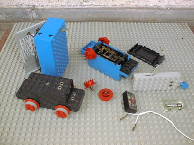
Lego® released their first motor (set number 100) in colours blue and black in 1966. It was a 4.5V battery supplied motor which used a special type of wheels that fall out of the motor housing easiely, when the o-rings, which hold the wheels shaft are fatigued. These first motors are easy to identify, since they are as high as four layers of bricks.
This motor type couldn't be opened by unwinding screws like the later ones. The blue one in the picture above is opened by the only possibility to get inside: brutal use of violence. It has metal gear wheels (, but later ones came with plastic gears either) and is made for long lasting use. A drop of oil placed at the sponge on top is all it needs for a couple of years.
The wheels have some kind of coupling at the end of their shaft. Even if the motor is heavy used: as long, as the small electric motor rotates, the wheels are forced to do the same! After all these years these motors are still very powerful. Used in a locomotive like the one from set 112 they are able to pull much more than any magnet coupling will bear.
The battery box is opened to the bottom and the connecting cable to the bottom contacts are cut easiely. The power supply cable had very simple contacs made from metal sheets without any insulation.
On the right hand you can see additional parts to spend some more functions to the trains: a break contact, a polarity changer (set 157) and a light brick.
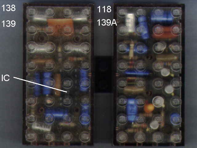
This scan of the Electronic Blocks (139 and 139A) shows what's the main difference: 139 (same as used in engine 138) has an additional IC in it's clear housing. Due to this superior technic it is able to drive an engine forward and backward, while prelimenary 139A (same as in engine 118) just drives and stops again. To find out more about the Electronic Trains, please follow the links above.

Here is a sideview of 139 and 139A. There is a funny detail about the contacts (all marked by red arrows): Although both blocks are roughly the same, the bottom contacts are on opposite sides. Just in conclusion a short table about the sets production years:
|
118:
138: 139A: 139: |
1968
1969 - 1971 1969 - 1970(?) 1969 - 1971 (sealed box with 1971 catalogue) |
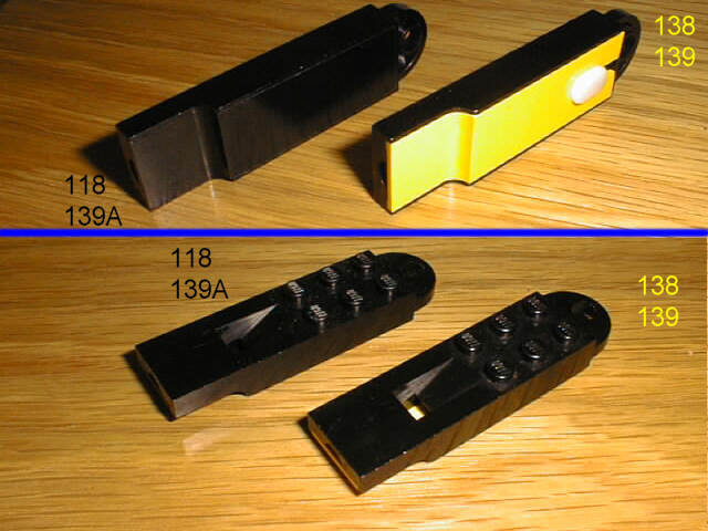
These two different whistles of the sets 118/139A and 138/139 are surly among the hardest to find Lego® bricks you can imagine. The whistle of set 138 came with a yellow bottom and a movable pin to tune up the frequency of the sound when the whistle is blown.

The next Lego® motor (set 103) was brought out only 3 years later in 1969. It has an height of 3 1/3 and came in colours blue and black again, but it has had the big advantage to become repaired very easiely. It has a housing which is closed with 4 screws: two on top and two in the bottom. The housing has still three connection points in shape of a pair of studs. Two of them on the very top. A improved batteriebox (still with contacts at the bottom side) could directy be attached there.
By adding an spare 12V motor one could upgrade set 103 from battery use to transformator use. Same couple was sold as set 702. The first sliding contacts (set 704) have had contacts made out of kid of chromed steel. And their contacts to the motor side have had the shape of a fir tree: even their position on top of the 2x4x1 brick became changed later...
The battery box of 103 opens to the top and is somewhat smaller than the later ones: battery size has grown somewhen during the seventies! But with AA type rechargable batteries you can drive these motors very cheap and without problems.
There have been some different kind of cables during the early 70ies: single plugs, coupled plugs, contacts made by metal shets and massive contacts either. The colour of the cables has always been white, the colour of the plug always blue, exept from set 118/138, where highly rare red plugs are used.
Next improvement in Lego® motor design was the possibility to drive a technic shaft (set 107, 1976). These new motors used only 2 screws on top, the bottom was attached by a kind of snap-on mount. They came in colours black and yellow; later ones are very rare. The motor has a new plug-in connection on the front side, but lost the contacts on the top instead. The contacts are no longer formed as studs.
The sliding contacts and the bricks to build an eight-wheeled engine changed their design too, but I have found no set numbers for these so far. The new sliding contacts (set 1151 / made from electric bronce) have more problems to cross points, but they have the advantage to fit to 103 and 107. The old ones could be used just with 103 type motors.
The new batterybox (colours black and grey) has more space for the newer bigger batteries, which have been invented these days, but they are simplified: there are no longer contacts on the bottom side.
This motor was sold as 12V version only till 1980. The 4.5V version was still used till the early 90ies, when Lego did a change to 9V battery boxes and 9V transformators.

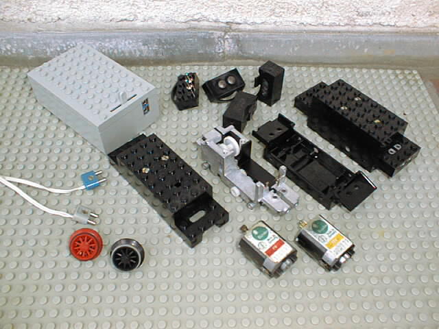
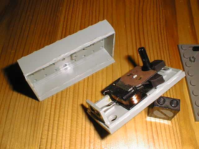
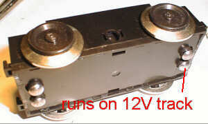
In 1980 the Lego Group invented their best train line. The new six wheeled 12V train motors from the picture above have been part of these train sets. They where very flat with a bogie on top, so they could be mounted directly under any long engine. Additionally they have had the possibility to add connecting rods. These motors came in colours black and rare red (only sets 7727, 7730 and 7750). The fitting valve blocks have been available in red also (sets 7715, 7722 and 7727).
A disadvantage of these motors is the missing of screws: they are glued together and hard to open.
On the left hand you can see an opened 12V train motor and you can guess why it is so heavy: in the inside there are massive metal structures. The power transmission is made very simple without any intershaft gears. Be careful with these motors: once opened with force, it is nearly impossible to close them again. You will have to glue the parts together, which requires a good adhesive.
The light systems was new in 1980 also: yellow light bricks for 4.5 Volt and white ones for 12V.
Additional note on 7865: there have been at least 3 versions of this motor:
The easily breakable bogie-pin on the top has been an extra part from this year on (as seen in the picture above on the red motor). In the earlier motors this pin was part of the top housing, which, however, meant it could break off easily. Later the pins' material was more elastic than the rest of the housing.
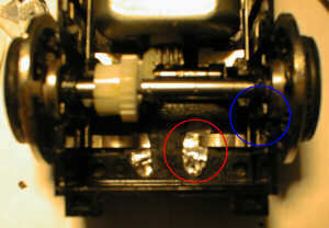
This defective point motor (7863) has been opened by Ludo Soete from Belgium, who sold it to me after the repair. These point motors have been used in the remote controlled points (7858/59), in the remote controlled decoupler (7862) and in the level crossing with electric gates (7866).
For this picture I have opened the housing again to make the view on the electrical and moving parts free. Especially the very thin wires from the contacts to the coil tend to break, but can be soldered with a quiet hand and some experience in such a job. To open a point motor withot damaging the housing seems to be hardly possible: Ludo did his job by cutting away the surrounding skirt - which is glued to the bottom part - on two sides. Maybe this picture can help you to do a more decent job. James Mathis has repaired such a point motor with help of the picture above: Maybe ask him for an instruction how to get inside that glued housing.
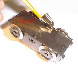
In 1991 there was the latest change to the new and still sold 9V system. The 9V train motors (set 5300) look quite similar to the 12V train motors (7765) from 1980, but they have not such a heavy weight, and only four steel wheels, which are at the same time the connecting contacts to the 9V track.

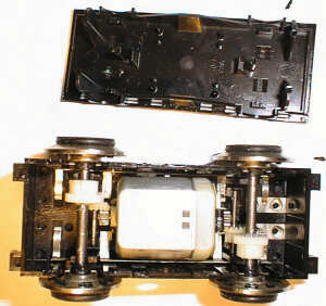
Here is the opened 9V motor. It uses one intershaft more than the 12V type, and it has no massive metal structures. Some of the photos down this page are a little fuzzy. If you have problems to see some details, this picture should help.
First you will have to open the motor housing. Are you ready to void
all your warranties? Okay - to open the housing it is very helpful (maybe
necessary) to reduce the size of the snap locks. You should cut nearly
half of every hook in longitudinal direction as shown in the picture above.
Do not cut to much because the hooks shall still do their work good enough
afterwards.

After doing so, you can go and open the housing: Best start on the end
side by pressing a as thin bladed knife as possible in the gap between
upper and lower part of the housing. Now the first snap locks should become
free, and the gap on the side of the motor become better visible. Do here
the same work. Before you have opened the housing completely, make sure,
the motor lies on it’s back. Otherwise all what’s inside may fell out and
you have to search on the floor for a while. Not speaking of cleaning these
parts... That’s what happened to me the first time I opened a motor!
Here lies the opened motor in front of you...
Do not turn it on its wheels! Some of the small parts may fall down.
On the one end of the motor you have to do nothing to get electric contact
(have a look 3 pictures further down). There are the contact points on
the outside. On the other side (shown in this photo) take some aluminum
wrap to make the electrical connection. In any way: be careful with the
small tiny stripes used as sliding contacts near the wheels (blue circle).
If you got out the wheel shaft by chance, put it back very carefully -
otherwise you may bend this small sheets.
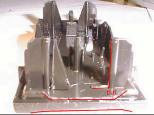
To get over crossings and conductor rails - not absolutely fixed to
the sleepers - it is better to cut of the downwards run around edge
in the front and back side of the bottom part of the housing. (In the picture
the red line at the bottom.) Additional several cuts have to be made on
the top side as it can be seen in the picture above too. The so won space
is for the sliding contacts to be built in.
Of course this work has be done not only in the front, but in the back
too.
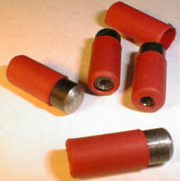
The sliding contacts need to have a diameter of not less than 5 mm;
otherwise you cannot run over points and crossings. For anything above
a diameter of 7 mm there’s not enough room. I choose to work with 6 mm.
The sliding contacts you can see here have a lengths of 16 mm. That’s the
right length to avoid them vanishing inside the motor completely. I made
them from a very weak iron of some rivets, as I didn't find some copper
round material.
The hemispheric shape is made by fixing the rivets (cut already to
right length) in a stationary drill. Under rotation I worked with a file
on it. The next step is to make a drill hole (as deep as possible; ca.
12 mm) for the springs that make the electric contact and hold the sliding
contacts down. The diameter of the drill hole depends on the springs diameter.
Try to use very soft springs: for example springs from a ball pen are to
strong, I think. Best diameter is smaller than the holes on the studs backside.
(or this end of the spring has to be bent in a way that it fits inside
this hole.) To avoid the sliding contacts leaving the motor housing the
red heat shrink tubes are applied here (you need them usually for electric
isolation). Made hot they stick very strong on the rivets iron.
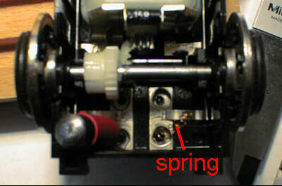
Here is shown how to build in the springs and sliding contacts on the
side, the connection cable can be mounted.
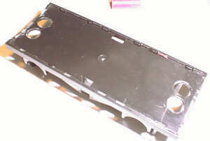
At last the drill holes in the housing are needed. Make them 0.2 mm bigger in diameter than the sliding contacts. The center of the holes should be ca. 4.5 mm away from the longitudinal symmetry line and ca. 5 mm from the end edges.
Now all works are finished! Putting things together might be a little tricky; maybe it will help to put a small string around the contacts.
Done!!
Be careful: this motor is still made for use with 9V; long lasting work under 12 V might be harmful for it.
Last (mini-)update: Jan. 2004